Search for
All you need
What do you need to look?
BONCHIP is GCT official authorized agent in China, spot supply RLP30 high power through hole PCB relay. RLP30 supports two contact structures of Form A single normal opening and Form C conversion, with rated load of 10A, peak value of 15A, unified coil power consumption of 360mW, voltage coverage of 5/12/24VDC; The whole machine has UL and TUV double certification, F-class insulation, anti-welding sealing shell is suitable for automatic production of wave soldering, 4kV pulse withstand voltage, suitable for HVAC, high-power household appliances, industrial power supply and industrial control main control board.
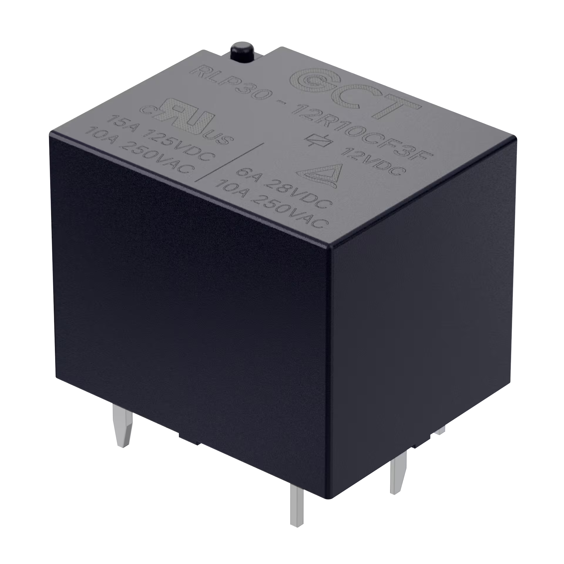
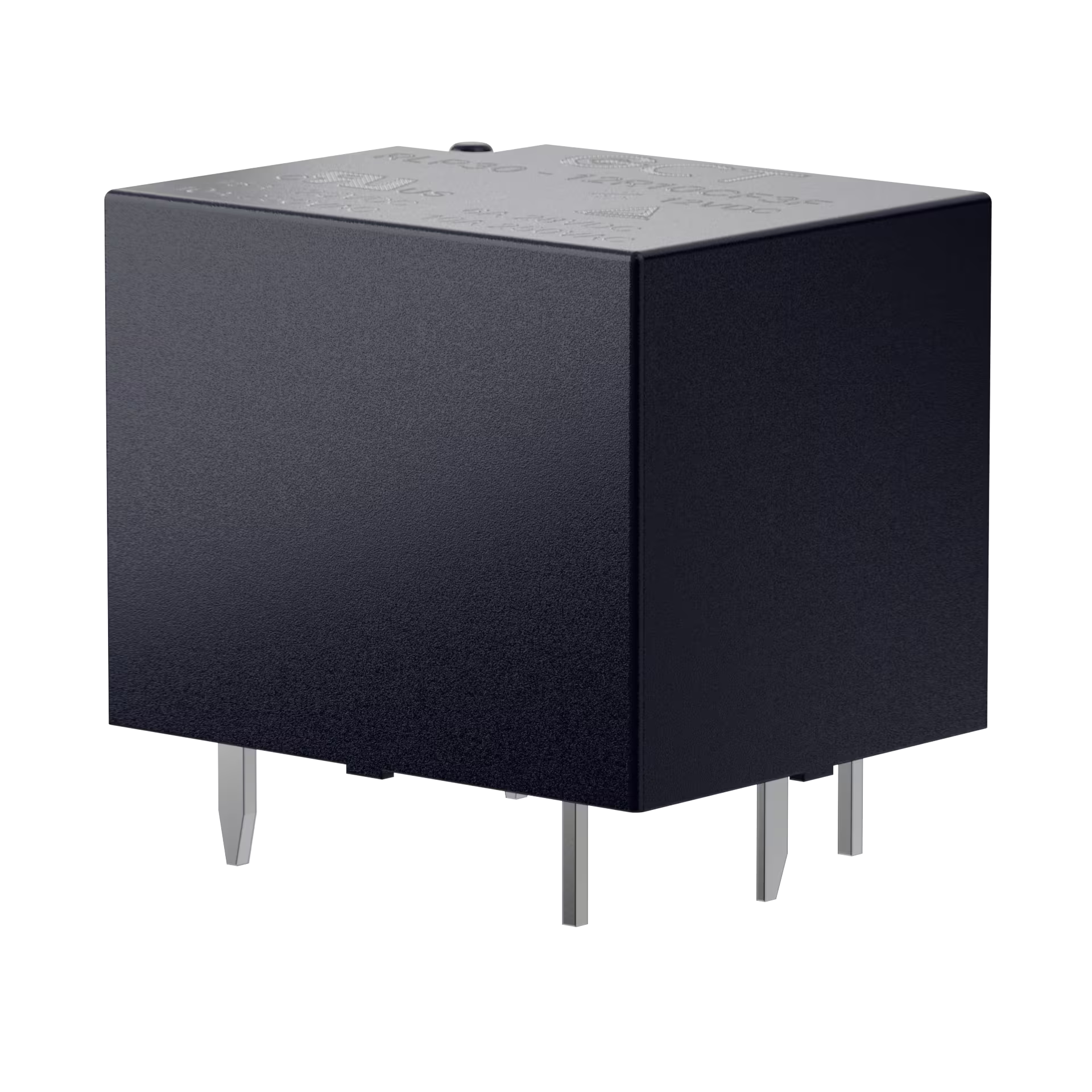
BONCHIP is an officially authorized Chinese distributor of GCT, offering in-stock RLP30 high-power through-hole PCB relays. RLP30 supports Form A single normal open and Form C conversion contact structures, with rated load of 10A, peak value of 15A, unified coil power consumption of 360mW, voltage coverage of 5/12/24VDC; The whole machine has UL and TUV double certification, F-class insulation, anti-welding sealed shell is suitable for automatic wave soldering production, 4kV pulse withstand voltage, suitable for power switching of HVAC, high-power household appliances, industrial power supply and industrial control main control board, support free sample application, batch stable supply, complete specifications and PCB packaging library.
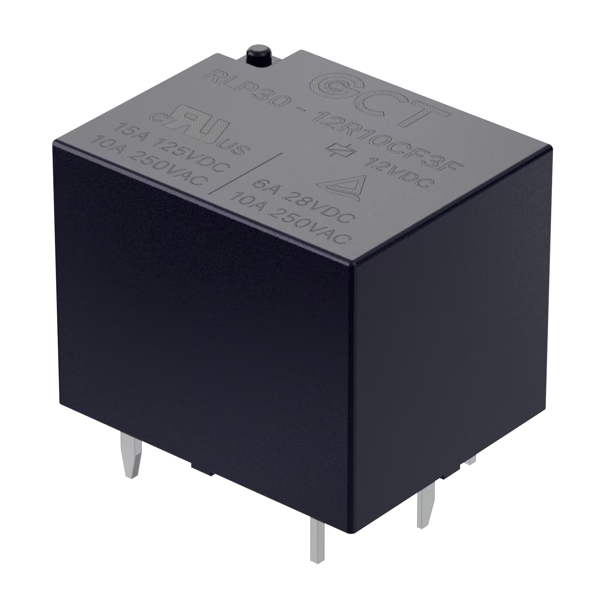
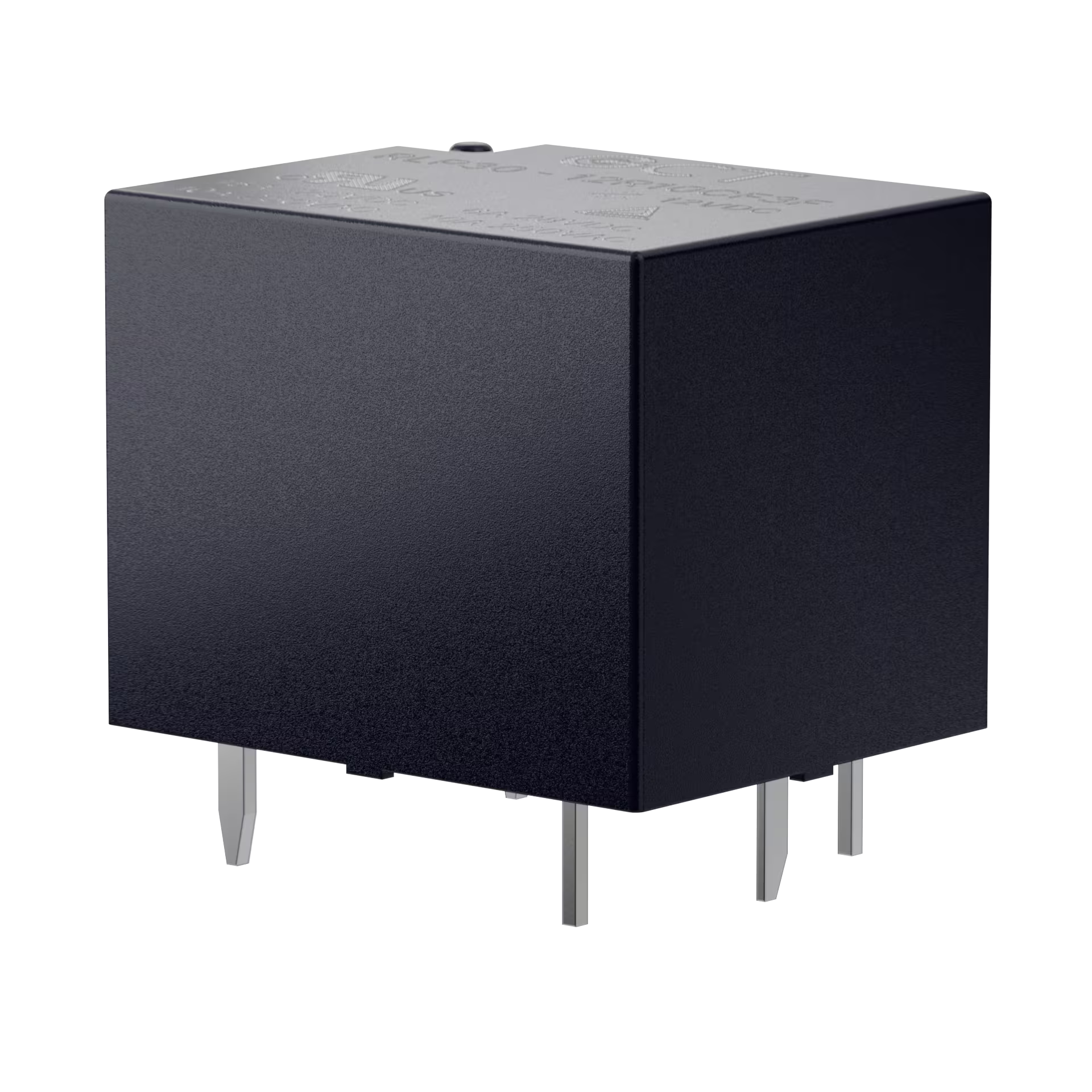
GCT RLP30 physical drawing
Product Model: RLP30
Standard load current 10A, short time peak 15A @ 125VAC
Support two contact structures: Form A single normally open (SPST-NO), Form C transfer contact (SPDT)
UL Class F High Temperature Insulation System
Non-magnetic holding type electromagnetic relay
With UL, TÜV double safety certification
Contact material: silver alloy AgSnO₂
Working environment temperature:-40 ℃ ~ 85 ℃
Working relative humidity: 20% ~ 85% RH
Storage environment: temperature 5 ℃ ~ 35 ℃, humidity 15% ~ 60% RH
Overall dimensions: length 19.2 × width 15.5 × height 15.25mm
Single weight: about 7.63g
Packing specifications: 50/pallet, 1000/box
Environmental compliance: RoHS compliance
RLP30: Product Series Code
XX: Coil rated voltage 03 = 3VDC / 05 = 5VDC / 09 = 9VDC / 12 = 12VDC / 24 = 24VDC
R10: Coil power consumption 360mW, standard 10A load specification
X: contact structure M = Form A single normally open; C = Form C switching contact
X: Enclosure Type F = Flux Tight / S = Fully Sealed
X: contact material 3 = AgSnO₂ silver tin oxide alloy
F: Insulation class F = UL Class F
| Material model | Coil voltage | Coil power consumption | Rated load | contact structure | Shell type | Contact material | Insulation class |
|---|---|---|---|---|---|---|---|
| RLP30-05R10MF3F | 5VDC | 360mW | 10A | Form A | Welding seal | AgSnO₂ | Class F |
| RLP30-12R10MF3F | 12VDC | 360mW | 10A | Form A | Welding seal | AgSnO₂ | Class F |
| RLP30-24R10MF3F | 24VDC | 360mW | 10A | Form A | Welding seal | AgSnO₂ | Class F |
| RLP30-05R10CF3F | 5VDC | 360mW | 10A | Form C Conversion | Welding seal | AgSnO₂ | Class F |
| RLP30-12R10CF3F | 12VDC | 360mW | 10A | Form C Conversion | Welding seal | AgSnO₂ | Class F |
| RLP30-24R10CF3F | 24VDC | 360mW | 10A | Form C Conversion | Welding seal | AgSnO₂ | Class F |
Note: The above table is the original factory general standard materials, stable inventory; non-standard custom specifications please contact the authorized agent BONCHIP to submit the application.
| Rated DC voltage of coil | Rated coil current (mA) | Minimum draw-in voltage (VDC) | Maximum release voltage (VDC) | Coil rated power consumption | DC resistance of coil (± 10%) | Maximum continuous coil voltage | Insulation class |
|---|---|---|---|---|---|---|---|
| 3VDC | 120 | 2.25 | 0.15 | 360mW | 25Ω | Rated voltage 130% | Class F |
| 5VDC | 72 | 3.75 | 0.25 | 360mW | 69 ohms | Rated voltage 130% | Class F |
| 9VDC | 40 | 6.75 | 0.45 | 360mW | 225Ω | Rated voltage 130% | Class F |
| 12VDC | 30 | 9.00 | 0.60 | 360mW | 400Ω | Rated voltage 130% | Class F |
| 24VDC | 15 | 18.0 | 1.20 | 360mW | 1600Ω | Rated voltage 130% | Class F |
| 48VDC | 7.5 | 36.0 | 2.40 | 360mW | 6400Ω | Rated voltage 130% | Class F |
15A @ 125VAC: electrical life 6000 times, on-off ratio 1s:9s; Mechanical life 10 million times
10A @ 250VAC / 6A @ 28VDC: electrical life 50000 times, on-off ratio 1. 5S: 1. 5S
Regular start 10A @ 250VAC: electrical life 50000 times
normally closed end 6A @ 28VDC / 6A @ 250VAC: electrical life 50000 times
Maximum switching voltage: 277VAC / 28VDC
Maximum switching current: 15A
Maximum switching power: 2500VA / 280W
Suction time: ≤ 10ms
Release time: ≤ 5ms
| Test items | Technical standard |
|---|---|
| Contact disconnect insulation resistance | ≥ 1000MΩ(500VDC test) |
| Initial contact resistance | ≤ 100mΩ(1A/5VDC test condition) |
| Inter-contact withstand voltage | 750V AC effective value, 1 minute |
| Coil and contact withstand voltage (function) | 1500V AC effective value, 1 minute |
| Vibration Test Standard | 10Hz ~ 55Hz, double amplitude 1mm, no abnormal function |
| Impact test | 10G (functional intact);100G (no structural damage) |
| Impulse resistance voltage | 4kV |
UL certification number: E550899
TÜV Certification Number: R507112480001
Creepage distance: 1.6mm
Electrical clearance: 3.2mm
Applicable pollution level: 3 industrial environment Remarks:
All performance test reference environment: coil temperature 23 ℃;
The parameters in the table are the initial factory performance of the product.
Overall shape: 19.2±0.5 × 15.5±0.5 × 15.25±0.5mm
Form A 4-pin PCB pad: 4 aperture Ø1.3 through holes
Form C 5-pin PCB pad: 5 aperture Ø1.3 through holes
Pin definition: 1/2 is coil pin, Form A 3 common end/4 normally open; Form C 3 Common End/4 Normally Open/5 Normally Closed
Electrical life derating curve: the greater the load current, the shorter the on-off service life of the relay, 15A only short-term peak use;
Coil temperature rise curve: power consumption is fixed at 360mW. The higher the ambient temperature, the higher the coil temperature rise. It is recommended to derate high-temperature equipment.
Version 0.7: 2026.04.10 First Draft of Internal Review
Version A: 2026.04.28 Officially Released