Search for
All you need
What do you need to look?
BONCHIP for GCT official authorized agent in China, spot supply RLP70 ultra-thin 7mm narrow body through hole relay. RLP70 focuses on high-density PCB miniaturization equipment, with a width of only 7mm and a coil power consumption of 200mW. It supports PWM holding voltage energy-saving control and pulse withstand voltage of 10kV. The load covers 5A/7A/10A, the contacts are made of AgNi and AgSnO₂, the full series of UL/TÜV certification, Class F high temperature insulation, and the anti-welding sealed housing is suitable for wave soldering mass production. Widely used in small industrial control
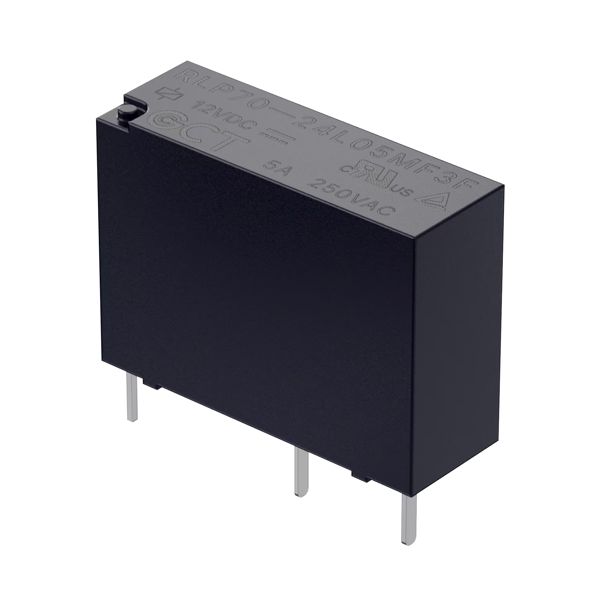
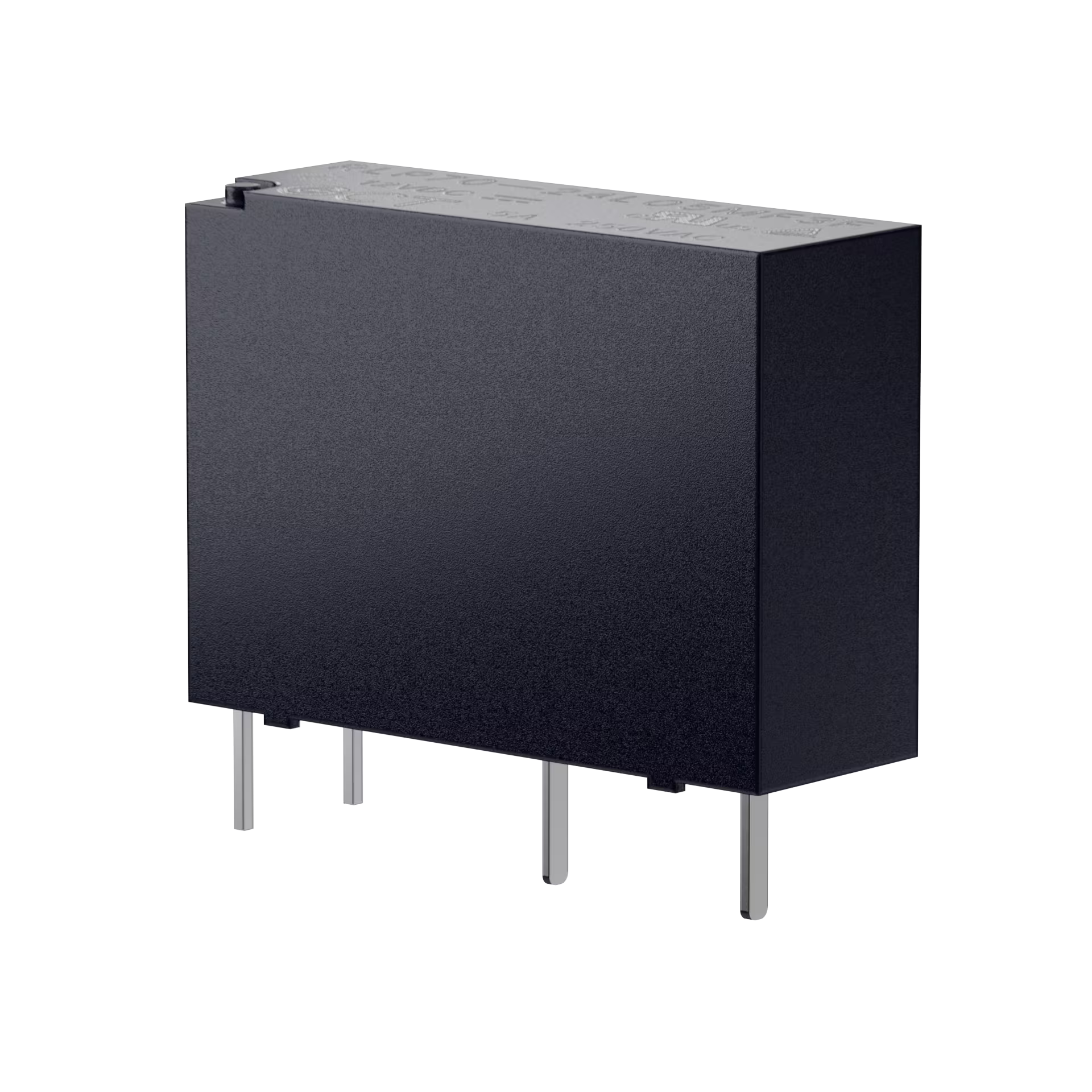
BONCHIP is the official authorized China distributor for GCT, offering in-stock RLP70 ultra-thin 7mm narrow-body through-hole relays. The RLP70 is a high‑density, miniaturized PCB‑mounted device with an overall width of just 7 mm. The coil consumes 200mW and supports PWM‑based hold‑voltage energy‑saving control, with a pulse withstand voltage of 10 kV. It covers load ratings of 5 A, 7 A, and 10 A, and its contacts are available in AgNi and AgSnO₂ materials. The entire series is UL/TÜV certified, features F‑class high‑temperature insulation, and comes in a solder‑resistant sealed housing suitable for wave‑soldering mass production. Widely used in small industrial control, portable equipment, smart home, high-density control board, can provide samples, complete specifications, PCB packaging library, batch delivery stability.
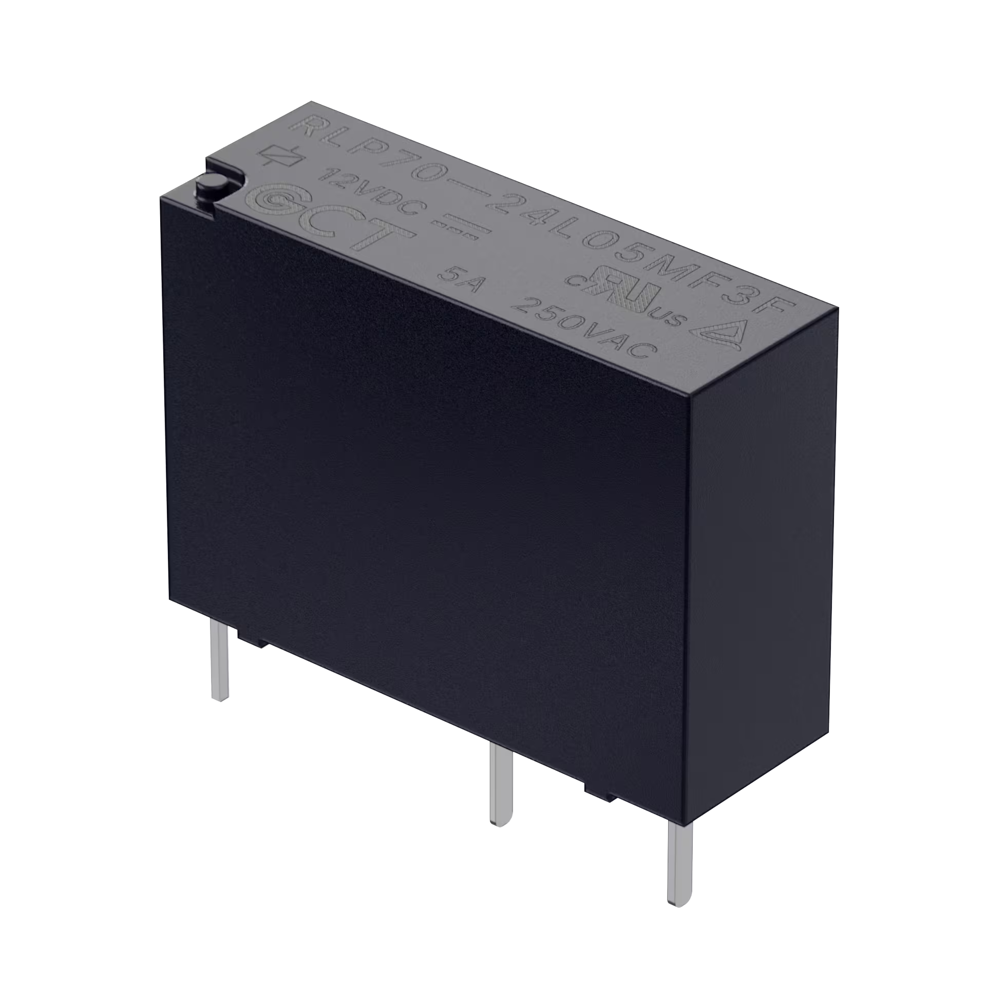
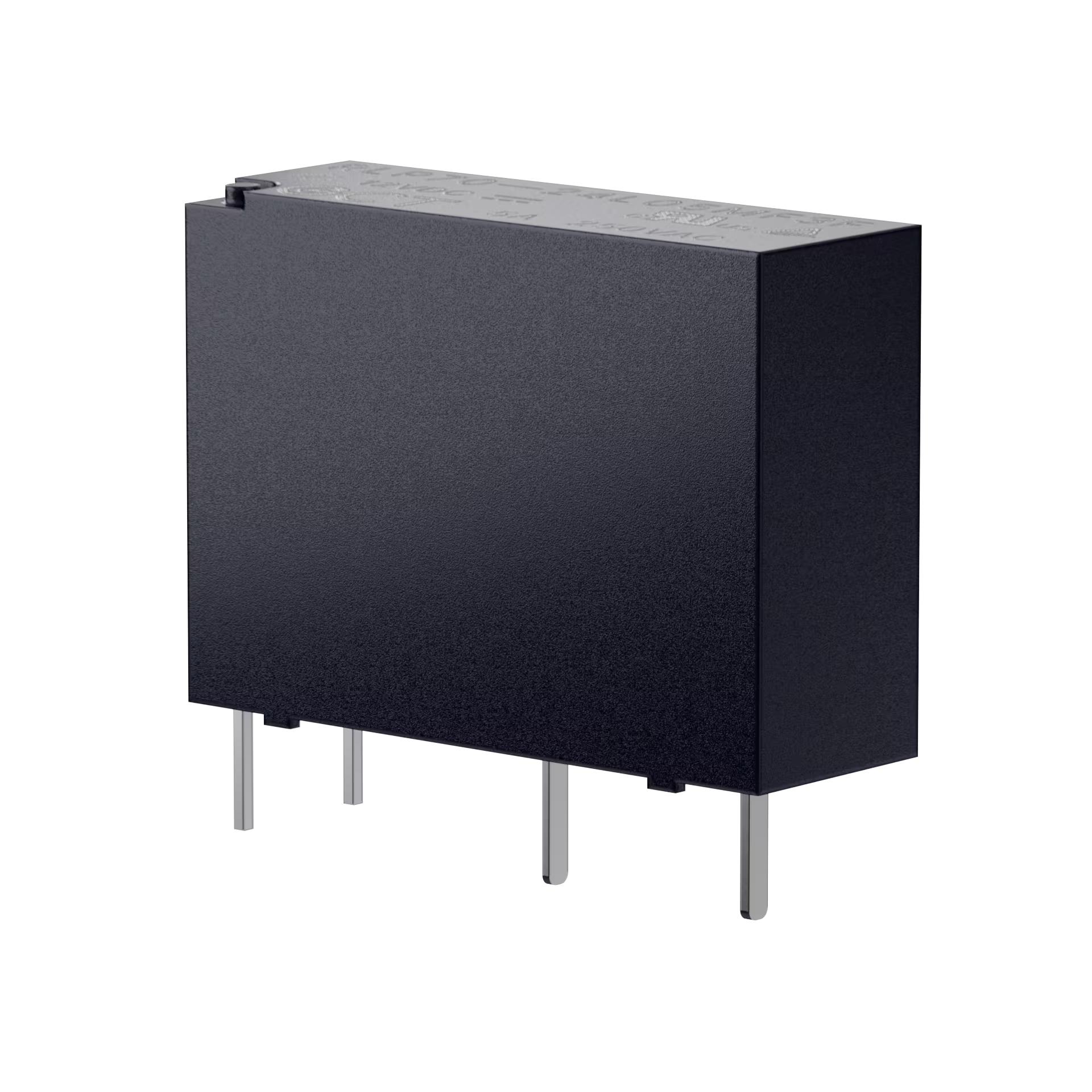
GCT RLP70 physical drawing
Product model: RLP70
Products Name: PCB Through-Hole Electromagnetic Relay
Load current covers 5A, 7A, 10A three gear specifications
Contact Architecture: Form A Single Normally Open (SPST-NO)
Pulse withstand voltage between coil contacts up to 10kV
The width of the whole machine is only 7mm, specially designed for PCB high density wiring
Support holding voltage, PWM energy-saving drive control, reduce coil power consumption
UL Class F High Temperature Insulation System
Non-magnetic holding type electromagnetic relay
UL, TÜV double safety certification
Contact material: silver alloy (AgNi/AgSnO₂)
Operating temperature range:-40 ℃ ~ 85 ℃
Working environment humidity: 20% ~ 85% RH
Storage conditions: 5 ℃ ~ 35 ℃, relative humidity 15% ~ 60% RH
Overall dimensions: length 20.4 × width 7.0 × height 15.0mm
Single product weight: about 3.68g
Packing specifications: 100/pallet, 1000/box
Environmental standards: comply with the RoHS directive
RLP70: product series code (7mm ultra-thin narrow body through hole relay)
XX: Coil rated voltage 03=3VDC,05=5VDC,06=6VDC,09=9VDC,12=12VDC,18=18VDC,24 = 24VDC
LXX: Coil power consumption 200mW, corresponding load current L05 = 5A,L07=7A,L10 = 10A
M: contact structure M = Form A single normally open SPST-NO
X: contact material 1 = AgNi silver nickel alloy/3 = AgSnO₂ silver tin oxide alloy
X: Enclosure Protection F = Flux Tight / S = Fully Sealed
F: Insulation class F = UL Class F
| Material model | Coil voltage | Coil power consumption | Rated load | contact structure | Shell | Contact material | Insulation class |
|---|---|---|---|---|---|---|---|
| RLP70-05L05MF3F | 5VDC | 200mW | 5A | Form A | Welding seal | AgSnO₂ | Class F |
| RLP70-24L05MF3F | 24VDC | 200mW | 5A | Form A | Welding seal | AgSnO₂ | Class F |
| RLP70-05L07MF3F | 5VDC | 200mW | 7A | Form A | Welding seal | AgSnO₂ | Class F |
| RLP70-12L07MF3F | 12VDC | 200mW | 7A | Form A | Welding seal | AgSnO₂ | Class F |
| RLP70-24L07MF3F | 24VDC | 200mW | 7A | Form A | Welding seal | AgSnO₂ | Class F |
Note: The above table is the original factory general standard materials, sufficient stock; non-standard voltage, sealed version can contact the authorized agent BONCHIP to apply for orders.
| Rated DC voltage of coil | Rated coil current (mA) | Minimum draw-in voltage (VDC) | Maximum release voltage (VDC) | Coil rated power consumption | DC resistance of coil (± 10%) | Maximum continuous voltage of coil | Insulation class |
|---|---|---|---|---|---|---|---|
| 3VDC | 66.7 | 2.25 | 0.15 | 200mW(40% holding voltage is only 32mW;50% holding voltage is only 50mW) | 45Ω | Rated voltage 160% | Class F |
| 5VDC | 40 | 3.75 | 0.25 | 200mW | 125Ω | Rated voltage 160% | Class F |
| 6VDC | 33.3 | 4.50 | 0.30 | 200mW | 180Ω | Rated voltage 160% | Class F |
| 9VDC | 22.2 | 6.75 | 0.45 | 200mW | 405Ω | Rated voltage 160% | Class F |
| 12VDC | 16.7 | 9.00 | 0.60 | 200mW | 720Ω | Rated voltage 160% | Class F |
| 18VDC | 11.1 | 13.5 | 0.90 | 200mW | 1620Ω | Rated voltage 160% | Class F |
| 24VDC | 8.3 | 18.0 | 1.20 | 200mW | 2880Ω | Rated voltage 160% | Class F |
AgNi silver nickel contact (5A/7A specification) load: 5A/7A @ 125/250/277VAC; Electrical life 50000 times (on and off 1s:9s); Mechanical life 5 million times
AgSnO₂ Silver Tin Oxide Contact (5A/7A/10A Full Specification) Load: 5A/7A/10A @ 125/250/277VAC; Electrical life 10000 times (on-off 1s:9s)
General Electric Index Maximum Switching Voltage: 277VAC / 30VDC Maximum Switching Current: 10A Maximum Switching Power: 2770VA / 150W Suction Time ≤ 10ms; Release time ≤ 10ms
| Test items | Standard parameters |
|---|---|
| Contact disconnect insulation resistance | ≥ 1000MΩ(500VDC test) |
| Initial contact resistance | ≤ 100mΩ(1A/5VDC test condition) |
| Inter-contact withstand voltage | 750V AC effective value, for 1 minute |
| Coil-contact function withstand voltage | 4000V AC effective value, for 1 minute |
| Vibration testing | 10Hz ~ 55Hz, double amplitude 1mm, no abnormal function |
| Impact (function) | 10G; destructive impact 100G |
| pulse withstand voltage | 10kV |
UL certification number: E550899
TÜV Certification Number: R507113940001
Creepage distance: 6mm
Electrical clearance: 6mm
Applicable industrial pollution level: Level 3 Remarks: All performance parameters are tested at the reference temperature of 23 ℃ coil, and the value is the initial performance of the product.
Overall shape: 20.4±0.5 × 7.0±0.2 × 15.0±0.3mm
PCB pad: 4-hole through-hole layout, recommended aperture Ø1.1mm
Pin definition: 1/2 coil pin, 3 common terminals, 4 normally open contacts (Form A single normally open)
Electrical life derating curve: the greater the load current of the contact, the service life of the switch is greatly shortened, and 10A is only used for a short time;
Coil temperature rise curve: the higher the power consumption of the coil, the higher the temperature rise. It is recommended to turn on PWM to maintain voltage energy saving mode in long-term high temperature scenarios.
Version 0.7: 2026.04.10 First Draft of Internal Review
Version A: 2026.04.28 Officially Released